Cooking Assistant for Automatic Temperature Control
Addition to cooking device that allows for automatic temperature-controlled cooking.
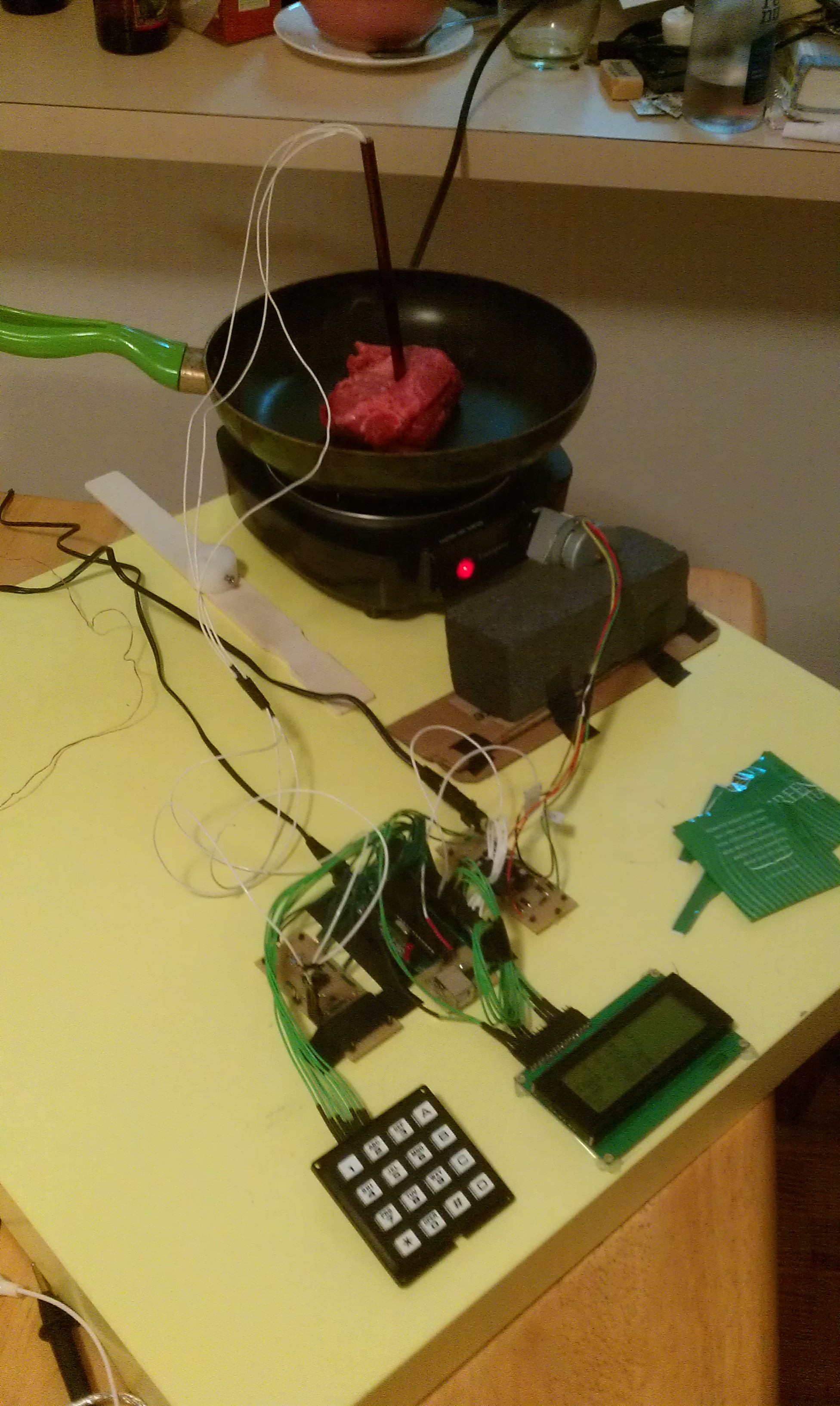
In some cooking scenarios, it is desirable to achieve a specific object temperature and keep the object at that temperature. However, it is difficult to maintain a constant temperature without constant attention. To aid cooking in this scenario, we created a device that can be added to an electric stovetop or hot plate and serve as an automated assistant.
The broad goals of our project were:
- measurement and control of a cooking device
- automated cooking of certain food types.
Once the device is attached to the dial of the electric burner, the desired position must be determined by a controller using temperature measurements. We have built two multi-purpose temperature probes. The first probe uses a temperature sensing integrated circuit (IC) which outputs a voltage proportional to the temperature in the range of -50C to +150C with 0.2C nominal resolution and limited error. The second probe uses a negative-temperature-coefficient (NTC) thermistor and is designed to operate from 0C to +200C with larger absolute error than the IC probe. A custom circuit was designed to precisely read the resistance of the NTC thermistor over the large range of 200ohms to 15000ohms with low current through the thermistor. Simply changing the resistance in series with the thermistor would lead to excessive current that would cause self-heating and damage of the sensor. The mechanical and thermal design of the temperature probes was very challenging. The probes needed to safely and quickly transfer heat from the object to the temperature sensor while not being severely affected by the environment temperature. After considerable amount of design work and one failed probe design, we came up with a probe and probe holder with the following characteristics:
- fast heat from object to sensor
- in presence of environment temperature much lower than object temperature, still has small offset between the object and sensor temperatures
- works for internal meat temperature and water temperature with various sized cookware
- simple and cheap to construct
Before the simulation can be conducted, the heat input from the electric burner must be found as a function of the dial position (set by the controller). Based on a 1.1kW peak electrical power rating of our hot plate, we assumed the maximum heat input to be 750W. We then assumed the heat input from the electric burner was linear with respect to the dial position. This assumption causes large inaccuracies in the predicted heat input, but it avoid us making a model of the electric burner that is both complicated and specific to the electric burner we purchased. During testing, not knowing the true heat input from the hot plate adversely affected the controller but the project still remained functional. Output calculation in the controller implementation on the MCU was done as a ratio of the maximum heat input. By modifying the QMAX symbol, the controller should scale properly. Output calculation also took into account the point at which the dial turns on. On our hot plate, the device is not on between "OFF" and "LOW." Therefore, we needed to add an offset to the controller output based on the latest calibration result of the minimum on state of the hot plate. The software section details these aspects, but these considerations do affect both the performance of the controller and the applicability of our project to other electric burners.
No comments:
Post a Comment